
 Business License
Blog Categories

Breathable Membrane Adoption in European Retrofit Projects
A contractor in Western Europe once retrofitted a cavity wall by filling the cavity and sealing the outer face, and found damp patches on the inner surface within a heating season. The wall had been made more airtight and had lost its path to dry, and a breathable membrane retrofit detail would have given the moisture somewhere to go.
European building retrofit has moved through a sequence of measures, and each one has changed the way the wall handles moisture. Insulation added to a wall makes the outer layers colder, sealing reduces the air movement that carried vapour away, and both effects increase the risk of condensation. This article covers how a breathable membrane retrofit addresses that, why the European building retrofit market has adopted it, and what a membrane energy performance figure does and does not describe.
1. Why European Building Retrofit Creates a Moisture Problem
European building retrofit usually adds insulation and reduces air leakage, and both measures change the moisture balance of the wall.
Insulation added to the outside of a wall moves the dew point inward, so the point at which the temperature falls below the dew point of the interior air moves closer to the inner face. Insulation added to the inside of a wall can move the dew point into or behind the insulation, where the moisture cannot dry.
| Retrofit Measure | Effect on Moisture |
|---|---|
| External insulation | Moves the dew point inward |
| Internal insulation | Can trap moisture in the wall |
| Cavity fill | Reduces the air gap that dried the wall |
| Air sealing | Reduces the air that carried vapour away |
| New windows | Reduces the ventilation that removed vapour |
The effect of the measures accumulates. A wall that has been insulated, sealed and fitted with new windows is warmer and more airtight than it was, and it has also lost the two mechanisms that dried it: air movement through the fabric and ventilation through the openings.
The result is a wall that uses less energy and traps more moisture. Where the moisture has no path outward, it accumulates and appears as a damp patch, a mould growth or a deterioration of the fabric. That is the problem that a breathable membrane retrofit is designed to solve.
2. Breathable Membrane Retrofit and the Drying Path
A breathable membrane retrofit provides a path for vapour to leave the wall while resisting the water that arrives from outside.
The membrane is installed on the outer face of the insulation, behind the cladding or the new render. It allows vapour to pass outward and resists liquid water, so the wall can dry to the exterior while rain is kept out.
| Function | Direction |
|---|---|
| Vapour transmission | Outward from the wall |
| Water resistance | Inward from the cladding |
| Air control | Through sealed laps |
| Wind washing | Reduces airflow in the insulation |
The vapour openness is the property that makes the retrofit work. A membrane with a high vapour resistance would block the drying path and reproduce the problem it was installed to solve, so the diffusion figure is the one that matters most in a retrofit application.
The membrane also provides air control where its laps are sealed. That function is what allows the assembly to be airtight without sealing the wall completely, because the membrane stops the air movement through the fabric while the vapour can still diffuse outward.
3. Membrane Energy Performance in a Retrofit
Membrane energy performance is often presented as a figure on its own, and in a retrofit it is a contribution to the assembly rather than a property that stands alone.
The membrane does not insulate. Its contribution to the energy performance of a wall comes from two effects: it allows the insulation to dry, which keeps the insulation at its rated performance, and it reduces the air movement through and around the insulation, which preserves the thermal performance that the insulation would otherwise lose.
| Effect | Mechanism | Result |
|---|---|---|
| Drying | Vapour passes outward | Insulation stays dry |
| Wind washing control | Reduces airflow in the insulation | Thermal performance retained |
| Air control | Sealed laps | Lower air leakage |
| Water resistance | Resists rain | Fabric stays dry |
A wet insulation performs below its rated figure, so a wall that traps moisture loses part of the benefit of the insulation that was added. The membrane contributes to the energy performance by keeping the insulation in the condition in which its figure applies, rather than by adding a thermal resistance of its own.
The air control contribution is a genuine saving, because air leakage carries both heat and moisture. A membrane with sealed laps reduces the leakage through the assembly, and the reduction appears in both the heating demand and the moisture load on the wall.
4. The European Building Retrofit Context
The European building retrofit market has adopted breathable membranes more widely than some other markets, and the reason lies in the age and construction of the existing stock.
A large share of the European building stock was built before modern insulation requirements, with solid masonry walls, with cavity walls, or with timber frames. Each of those constructions behaves differently when it is retrofitted, and each creates a different moisture risk.
| Construction | Retrofit Risk |
|---|---|
| Solid masonry | Moisture trapped by internal insulation |
| Cavity wall | Cavity fill reduces the drying gap |
| Timber frame | Framing moisture behind new cladding |
| Mixed construction | Different behaviour in one wall |
The retrofit programmes have also been driven by energy targets, which push the insulation levels higher and make the moisture risk greater. A modest addition of insulation changes the moisture balance slightly, and a deep retrofit changes it substantially.
The adoption of the membrane has therefore followed the depth of the retrofit. A shallow measure can often be completed without one, and a deep retrofit that adds insulation to the outside and seals the wall generally needs a drying path that the membrane provides.
5. Case Notes on a Breathable Membrane Retrofit
A contractor in Western Europe retrofitted a cavity wall by filling the cavity and sealing the outer face, and found damp patches on the inner surface within a heating season. The wall had been made more airtight and had lost its drying path. Adding a breathable membrane behind a new outer render restored the drying path and the damp patches did not return.
A second project added internal insulation to a solid masonry wall and found the insulation damp at its outer face after a winter. The dew point had moved into the insulation and the moisture had no path outward. The detail was reworked to allow the wall to dry to the outside, and the insulation stayed dry. The membrane was part of the corrected detail rather than an addition to the original one.
Both cases show the same point. A retrofit that reduces the drying capacity of a wall has to provide a replacement path, and the membrane is the component that provides it.
6. Specifying a Retrofit Membrane
Specify the diffusion figure first, because the vapour openness is the property that the retrofit depends on.
Specify the water resistance against the exposure at the site. A wall that faces driving rain needs a higher figure than a sheltered one, and the exposure should be assessed rather than assumed from the building type.
Specify the laps and the tape where the membrane is also the air barrier. The air control function depends on the laps being sealed, and an unsealed lap leaves both the air control and a local moisture path.
Specify the position of the membrane in the build-up, and check the whole assembly against the direction of the vapour drive. A membrane on the wrong side of the insulation blocks the drying path rather than providing it.
7. Membrane Energy Performance Mistakes in a Retrofit Assembly
The common mistakes in a breathable membrane retrofit are layer and detail mistakes rather than product mistakes, and each of them reduces the membrane energy performance that the design assumed.
The first is a membrane with too high a diffusion resistance, which blocks the drying path and reproduces the problem the retrofit was meant to solve. The second is a membrane placed on the wrong side of the insulation, which traps vapour instead of releasing it.
The third is an unsealed lap where the membrane is also the air barrier. The air control function then fails at that point, and the moisture carried by the leaking air arrives at a surface that has been assumed to be protected.
The fourth is a detail that interrupts the membrane at an opening or a penetration. Each interruption is a local failure of both the water resistance and the air control, and the details are where the wall is most likely to be wetted.
8. Breathable Membrane Retrofit Supplier Profile
United Perfect Building Materials, part of Jinan United Perfect Building Materials Corporation, produces breathable membranes for wall and roof systems and supplies buyers in Europe. The company quotes the water resistance and the diffusion resistance of each grade on a stated basis, which allows a breathable membrane retrofit to be specified against the exposure at the site and the drying requirement of the wall.
Jinan United Perfect Building Materials holds retained samples by production batch, so a delivered roll can be checked against the reference used at approval. Buyers planning a european building retrofit can confirm the diffusion figure in writing, and can order the jointing tapes with the membrane where the assembly has to be airtight. United Perfect can also advise on the position of the layer where an existing wall has been insulated and sealed.
9. FAQ About Breathable Membrane Retrofit
9.1 Why does retrofitting need a breathable membrane?
Because a retrofit usually reduces the drying capacity of the wall at the same time as it reduces its energy demand. Insulation moves the dew point inward, cavity fill removes the air gap that ventilated the wall, and air sealing removes the air movement that carried vapour away. Where the moisture has no path outward, it accumulates and appears as a damp patch or a mould growth. A breathable membrane retrofit provides a path for vapour to leave the wall while resisting the water that arrives from outside.
9.2 Does the membrane itself save energy?
It does not insulate, and it contributes to the energy performance of the assembly in two indirect ways. It allows the insulation to dry, so that the insulation stays at the figure it was specified to meet, because a wet insulation performs below its rated value. It also reduces the air movement through and around the insulation, which preserves the thermal performance that the insulation would otherwise lose. The membrane energy performance figure is therefore a contribution to the assembly rather than a resistance of its own.
9.3 Can a breathable membrane be used with internal insulation?
It depends on where the membrane sits and on the direction of the vapour drive. Internal insulation can move the dew point into or behind the insulation, where the moisture cannot dry toward the interior, and the assembly then has to be able to dry to the outside. A membrane on the outer face provides that path. A membrane on the inner face of an internally insulated wall can trap the moisture in the wall, which is the risk that the detail has to avoid.
9.4 What diffusion figure should I choose?
It follows from the drying requirement of the wall rather than from a single figure. A retrofit needs a membrane open enough to let the wall dry outward, because a membrane with a high diffusion resistance blocks the path and reproduces the problem it was installed to solve. The figure should be checked against the whole assembly and the direction of the vapour drive for the specific building. The supplier should quote it on a stated basis so that it can be compared.
9.5 Where does the membrane go in a retrofit?
On the outer face of the insulation, behind the cladding or the new render, so that vapour can pass outward and rain is kept out. The position follows the direction of the vapour drive, which in most European heating climates runs from the warm interior toward the cooler exterior. Placing the membrane on the wrong side of the insulation blocks the drying path and traps vapour in the wall. The layer position should be checked against the assembly rather than taken as a standard rule.
Recently Posted
-
From Felt to Synthetic Underlayment in North American Roofing
November 3, 2026A roofing supplier in North America once kept both felt and synthetic underlayment on the same rack and watched the split shift wi Read More
-
QC Checklist for Synthetic Underlayment Before Shipment
November 3, 2026A buyer in North America once received a shipment in which the lengths on the packing list were correct and the rolls at the centr Read More
-
Synthetic Underlayment Slitting Winding and Roll Diameter Control
November 2, 2026A buyer in North America once rejected a container of synthetic underlayment because the rolls at one end had flattened into an ov Read More
-
Synthetic Underlayment for Tropical and Desert Roofing Projects
November 2, 2026Two projects in the same product family can fail for opposite reasons. A tropical roof underlayment in Southeast Asia can be ruine Read More

Contact Us
Recommended Products
-
 Glasswool Blanket With FSK FacingNegotiableMOQ: 100 Rolls
-
Rockwool Blanket With Wire MeshNegotiableMOQ: 100 Rolls
-
Rockwool Blanket With FSK FacingNegotiableMOQ: 100 Rolls
-
CE Certified Glass Wool Insulation, Glasswool Fiberglass, Low Thermal Conductivity, Noise Reduction for Wall, Roof and Industrial EquipmentNegotiableMOQ: 100 Rolls
-
KSK Foil Facing Roll, Laminated Aluminum Foil + Scrim + Kraft Paper, Anti-Tear Thermal Barrier, Suitable for Commercial HVAC and Roof InsulationNegotiableMOQ: 500 Rolls
-
FSK Foil Scrim Kraft, FWF MSK MWV KSK Laminate Foils, Metalized PET MPET Vapor Barrier Facing for Insulation Glasswool RockwoolNegotiableMOQ: 100 Rolls
-
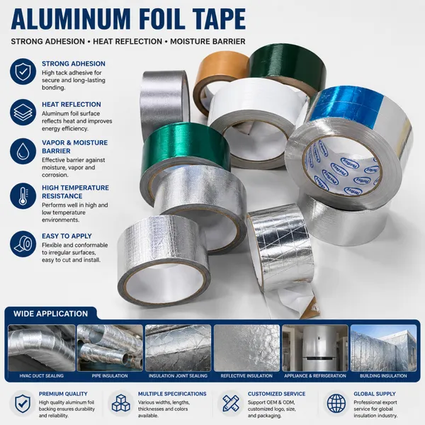
Reinforced Aluminium Foil Tape, Waterproof Anti-aging Tape, Widely Used in HVAC and Building Insulation ProjectsNegotiableMOQ: 500 Cartons
-
HVAC Aluminum Foil Sealing Tape, Strong Adhesion Heat Resistance for Pipe, Glass Wool and Rockwool InsulationNegotiableMOQ: 500 Cartons
-
Factory Supply Metalized PET MPET Laminate Foils, Aluminum Coated PET Film for Roof Wall InsulationNegotiableMOQ: 10000 Cubic Meters
-
Custom MPET Metalized PET Laminate Foils, VMPET Metallized Polyester Facing Film for Thermal InsulationNegotiableMOQ: 10000 Cubic Meters
-
Glass Wool Insulation Series, Glasswool With FSK/FWF/MSK/MWV/KSK Facing, Metalized PET Laminate Foils, Heat & Sound Insulation for Commercial BuildingNegotiableMOQ: 100 Rolls
-
Rockwool Blanket With Black Firber GlassNegotiableMOQ: 100 Rolls
-
Glasswool Insulation Blanket & Board, FSK FWF MSK MWV KSK Foil Laminate, MPET Metalized PET Faced Glass Wool for HVAC, Roof, Wall, Air DuctNegotiableMOQ: 100 Rolls
-
Rockwool Insulation Roll, FSK Foil Faced Mineral Wool for Building Thermal & Acoustic Insulation, Fire Resistant Roof Wall Insulation MaterialNegotiableMOQ: 100 Rolls
-
FWF MSK FSK Foil Laminated Rock Wool Glass Wool Blanket, Metalized PET Laminate Foils Faced Insulation for HVAC and ConstructionNegotiableMOQ: 100 Rolls
-
Rockwool Insulation Board, Mineral Wool Rock Wool Slab for Building Thermal & Fire Insulation, Soundproof Rockwool Panel for Roof, Wall, HVAC SystemNegotiableMOQ: 100 Rolls
-
Rockwool Pipe Section, Mineral Wool Rock Wool Tube Insulation, Fire & Heat Resistant Rockwool for Steam Pipes, Industrial Pipeline Insulation ProjectNegotiableMOQ: 100 Rolls
-
Rockwool Board With FSK FacingNegotiableMOQ: 100 Rolls
-
Rockwool Insulation Slab With FSK Facing, Fireproof Rock Wool Board, Thermal & Sound Insulation Rockwool for Roof, Wall and Ductwork ApplicationNegotiableMOQ: 100 Rolls
-
Fireproof Foil Laminated Glass Wool, Laminate Foils MPET Faced Glasswool Insulation Roll & Sheet for Roofing, Wall, Duct and Pipe InsulationNegotiableMOQ: 100 Rolls